Table of Contents
Types of Gear: Best Fit for High Torque
1. Introduction to High Torque Gear Selection
Defining high torque in mechanical power transmission
When we talk about high torque in the realm of mechanical power transmission, we are essentially describing a rotational force that would make most standard drivetrains throw in the towel—think of it as the grunt required to turn a massive cement mixer drum from a dead stop or the jaw‑dropping twist needed to rotate the main rotor of a wind turbine against a gale‑force wind. In more technical terms, torque is the product of tangential load and pitch radius, often expressed in Newton‑meters or pound‑feet, where values exceeding several thousand Nm demand an entirely different design philosophy. High torque scenarios are characterized by low to moderate rotational speeds, substantial inertial loads, and the kind of stress that separates real engineering from mere tinkering. Understanding torque as a physical quantity is the very first step before even glancing at a gear catalog.
Why gear type directly impacts torque capacity and efficiency
Here is the rub: not all gear geometries are created equal when the load gets heavy. How teeth mesh, slide, and transfer force fundamentally alters stress distribution, contact ratios, and frictional losses. A helical gear spreads load gradually across multiple teeth, reducing peak stress, whereas a spur gear slams all the force onto a single line of contact. Planetary arrangements split torque among several planet gears, effectively multiplying capacity without increasing diameter. The gear type you choose determines not just whether your gearbox survives, but also how much energy gets wasted as heat and whether your procurement budget goes up in smoke from premature failures.
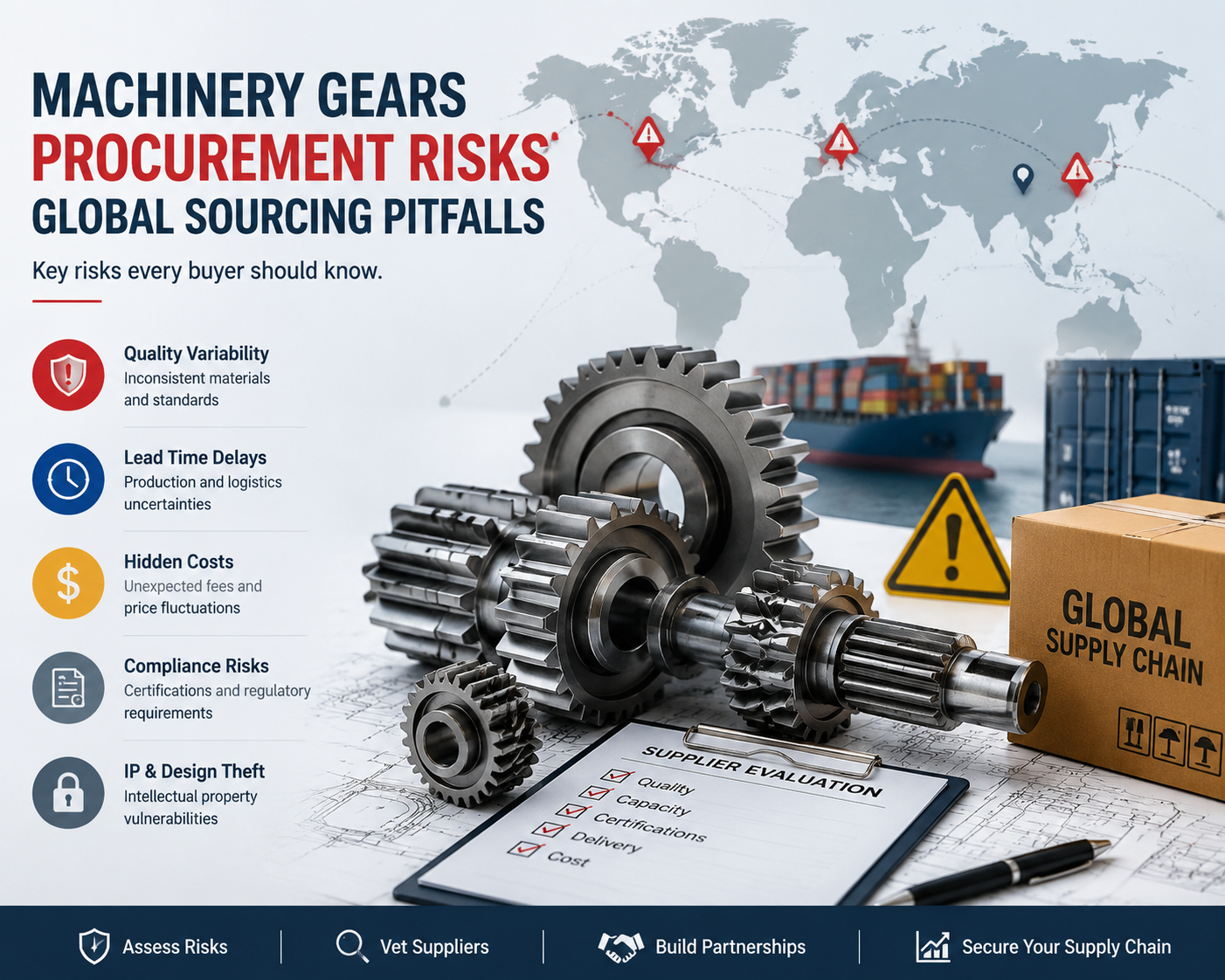
Overview of application risks from improper gear choice
Picking the wrong gear type for high torque is a bit like using a butter knife to chop firewood—sooner or later something will shatter. The risks range from tooth breakage from bending fatigue to surface pitting that turns gear flanks into lunar landscapes, or even scuffing that welds teeth together in a microsecond. Downstream chaos includes downtime measured in days, replacement parts stuck in a six‑week lead time, and procurement professionals getting grilled in post‑mortem meetings—all of which can be avoided by understanding the nuanced trade‑offs between gear families from the very beginning.
2. Helical Gears for High Torque
Load distribution advantages of helical tooth engagement
Helical gears bring progressive load sharing to the table: because their teeth are cut at an angle, they engage gradually rather than all at once, like easing a zipper closed instead of slamming a door. This obliquity means multiple teeth remain in contact at any moment, distributing high torque load across a wider surface area and reducing peak Hertzian contact stress. Helical gears can transmit 30‑40% more torque than a spur gear of identical size and material, making them the go‑to choice for heavy‑duty conveyor drives, extruders, and rolling mills where steady, high torque is the daily bread.
Axial thrust considerations and bearing requirements
Now for the kicker: that same helix angle generates significant axial thrust along the gear shaft—the gears try to climb off each other, pushing against bearings and housing. You will need thrust bearings, often angular contact ball bearings or tapered roller bearings, rated for that additional axial load. The housing must be stiff enough to prevent deflection under combined radial and thrust forces, because any misalignment will instantly ruin the contact pattern and send your torque capacity down the drain.
Typical torque limits and efficiency ranges
In practical terms, helical gears handle from 1,000 Nm up to well over 100,000 Nm in industrial reducers, with efficiency between 94% and 98% per stage for properly lubricated, ground‑finished gears. The axial thrust introduces some extra sliding friction compared to spur gears, but for most high torque applications the trade‑off is well worth it. You get smooth, quiet operation, excellent torque density, and the ability to use higher reduction ratios in a single stage—just keep an eye on heat generation from thrust bearings.
3. Spur Gears Under Heavy Load
Simplicity and cost effectiveness for moderate high torque
Sometimes the old ways are the best. Spur gears, with straight teeth cut parallel to the shaft axis, are the blue‑collar workhorses of the gear world—they offer simplicity, low manufacturing cost, and no axial thrust. For moderate high torque applications where budget constraints are tight, the initial gear cost per Nm is often the lowest among all gear types.
Tooth root stress and fatigue failure points
Here is where rubber meets the road: spur gears suffer full‑face instantaneous contact, slamming the entire tooth width into engagement at once and creating a shock load that concentrates stress at the tooth root fillet. Under high torque cyclic loading, this stress becomes a fatigue crack nucleation site, eventually leading to tooth breakage. The Lewis form factor and AGMA bending stress calculations become your best friends—if you underestimate torque or use substandard material, you will have no warning, just a sudden loud snap.
Noise and vibration trade-offs at high torque
And if mechanical failures weren’t bad enough, spur gears at high torque produce significant acoustic emission—a howling, whining din that can reach 95 decibels. Instantaneous line contact and variable stiffness generate strong transmission error and vibration at mesh frequency and harmonics. This not only annoys everyone nearby but also transmits torsional vibrations into your motor and driven equipment, causing premature bearing wear, coupling fatigue, and structural resonance.
4. Planetary Gear Systems for Extreme Torque
Torque density benefits of multiple load paths
When torque requirements go off the charts—500,000 Nm for a tunnel boring machine—you simply cannot beat planetary gear systems. Input torque routes through a sun gear, which drives three to five planet gears orbiting around it, all sharing the load before transferring to a stationary ring gear. This multiplies torque capacity by the number of planet branches without increasing diameter, achieving 2 to 3 times the torque per unit volume compared to parallel‑shaft helical reducers. That is why you find them in wind turbine yaw drives, mining haul trucks, and excavator slewing drives.
Compact footprint for high torque industrial applications
The beauty of a planetary gearbox is that you can stuff enormous torque into a small cylindrical package that fits inside a wheel hub or mounts directly to a motor flange. A planetary stage with 5:1 ratio and four planets might handle 20,000 Nm in a housing just 300 mm in diameter, whereas a comparable helical gearbox would need three stages and take three times the length.
Lubrication and heat dissipation challenges
But hold your horses—that compactness comes with thermal management headaches. Getting oil to all meshing interfaces and extracting heat is genuinely complex, especially as planets spin on their own bearings and rotate around the sun. Forced circulation with an external pump, heat exchanger, and carefully designed oil galleries is often mandatory. Trapped heat can spike oil temperatures above 100°C, thinning viscosity until you get boundary lubrication and scuffing failure. Never skimp on thermal analysis.
5. Bevel Gears in Right‑Angle High Torque Drives
Torque handling differences between straight and spiral bevel
When your drivetrain needs to turn a corner without losing its cool, bevel gears are the ticket. Straight bevel gears with abrupt tooth engagement handle high torque only at low speeds and with generous safety margins. The real champion is the spiral bevel gear, whose curved teeth engage progressively like helical gears, distributing load across multiple teeth and reducing stress concentrations. Spiral bevels routinely handle 5,000 Nm to over 100,000 Nm in helicopter tail rotor drives, marine outdrive units, and heavy industrial mixers.
Mounting precision requirements to avoid edge loading
Now for the painful truth: bevel gears, especially spiral ones, are unforgiving divas when it comes to mounting accuracy. Any axial or radial misalignment shifts the contact pattern toward the toe or heel, causing edge loading that concentrates all torque onto a tiny sliver of tooth flank. This leads to rapid pitting, chipping, or tooth fracture in hours rather than years. Precision ground mounting shoulders, matched bearing sets with preload, and a housing that does not deflect under load are non‑negotiable.
Typical torque ratings for mining and heavy equipment
Despite these demands, properly designed spiral bevel sets are the backbone of right‑angle drives in the toughest industries—mining shuttle cars, continuous miners, heavy‑duty forklifts, and crane slew drives routinely use bevel gears rated from 20,000 to 150,000 Nm. Demand AGMA quality class 10 or higher, full case hardening and grinding, and 100% inspection of contact patterns and tooth spacing. A cheap bevel gear is the most expensive component you will ever buy.
6. Worm Gears: High Torque with Speed Reduction
Self-locking behavior under high torque loads
Worm gears occupy a strange and wonderful niche: their sliding action—a hardened steel worm turning against a bronze wheel—creates a natural self‑locking characteristic when the lead angle is small. Once you stop driving the worm, the load cannot back‑drive the system. For hoists, elevators, and conveyor incline sections, this feature is pure gold. Ratios from 20:1 up to 100:1 in a single compact stage are possible, saving you the cost of external brakes.
Efficiency losses and thermal management needs
However—and this is a big however—that beautiful sliding action comes at a horrific efficiency penalty. Coefficients of friction as high as 0.05 to 0.10 lead to efficiencies that can drop below 50% for high‑ratio, high‑torque configurations. Half your input power turns directly into heat, turning your gearbox into a miniature furnace. Forced cooling—fans, water jackets, or separate oil coolers—is absolutely required to keep lubricant from oxidizing and the bronze wheel from annealing.
Material pairing for bronze-steel interfaces
The classic pairing is a hardened and ground steel worm (case‑hardened to 58‑62 HRC) running against a centrifugally cast bronze wheel, usually phosphor bronze or aluminum bronze. Dissimilar materials reduce galling and allow the worm to lap a conformal fit into the softer bronze over time. But bronze is expensive and has limited strength; torque ratings typically top out around 10,000 to 20,000 Nm. Exceed that, and the bronze wheel will overheat, soften, and eventually extrude material—a spectacular failure mode.
7. Material Selection Impact on Torque Capacity
Case-hardened vs through-hardened steel gears
Let us talk steel—how you treat it matters enormously. Case‑hardening (carburizing or carbonitriding) gives a glass‑hard surface of 58‑62 HRC over a tough ductile core, while through‑hardening (quench and temper) provides uniform hardness of 30‑45 HRC from surface to center. For high torque where contact stresses can exceed 1,500 MPa, case‑hardened gears dominate. A carburized gear set can handle three to four times the torque of a similar through‑hardened set, making the extra heat treatment cost seem like a bargain.
Surface treatments like nitriding or carburizing
Beyond bulk hardening, surface engineering works magic. Nitriding forms a hard, wear‑resistant case without distortion, though the case is thin (0.3‑0.6 mm) and can crush under extreme contact loads. Carburizing gives a deeper case of 1‑2 mm, ideal for large gears, but requires expensive grinding. Induction hardening offers selective tooth flank hardening. For the highest torque densities, superfinishing (isotropic superfinishing) reduces roughness below 0.05 Ra, boosting scuffing resistance by up to 300%.
Powder metal limitations for high torque applications
A cautionary tale for procurement: while powder metallurgy has improved with high‑density processing, even the best PM gears have residual porosity (2‑5%) and lack directional grain flow. They are inherently weaker under high torque cyclic bending and contact stresses. You might get away with PM gears for moderate torque under 500 Nm, but push them to 2,000 Nm or higher and pores become fatigue crack initiation sites. Stick with wrought steel for high torque—there is no substitute.
8. Gear Tooth Geometry and Torque Distribution
Pressure angle effects on load carrying capacity
The pressure angle is not just a number; it directly influences how much torque you can push through a gear pair. Standard 20° pressure angles balance contact ratio against bending strength. Larger 25° pressure angles create thicker teeth that are significantly stronger in bending, allowing you to handle higher torque without increasing face width or module. For the very highest torque applications, 25° or even 28° pressure angles can boost torque capacity by 15‑20% compared to 20° designs—though you will pay with louder operation and higher bearing loads.
Profile modification to reduce stress concentrations
Tip and root relief—small intentional deviations from the perfect involute profile—work wonders for torque distribution. Under high torque, a gear tooth bends elastically, moving its tip away from the ideal position and creating leading‑edge contact that generates stress spikes. Properly designed relief of 0.01‑0.05 mm ensures smooth entry and exit from contact, distributing load across the entire flank and reducing peak contact stress by as much as 30%.
Face width optimization for torque transmission
Wider teeth seem like an obvious way to increase torque capacity, but beyond a face‑width‑to‑pitch‑diameter ratio of about 1.5:1, you run into diminishing returns. Manufacturing errors, shaft deflection, and housing twist cause uneven load distribution, leaving one end of the tooth carrying all the torque. The optimal face width usually lands between 0.8 and 1.2 times the pitch diameter. If you absolutely need more torque, increase the module or switch to a stiffer gear material rather than just making the face wider.
9. Manufacturing Tolerances for Reliable High Torque
AGMA quality class requirements above Q10
The AGMA quality class is a direct predictor of how a gear will behave under high torque. Classes below Q8 are only for low‑speed, low‑torque applications. High torque demands Q10, Q11, or even Q12, which specify tooth spacing errors below 10 microns, profile deviations under 5 microns, and lead errors measurable only with lasers. Achieving Q10 or higher requires grinding every tooth flank after heat treatment, adding 30‑50% to the cost—but the payoff is uniform load distribution, predictable fatigue life, and the ability to run at higher torques.
Runout and backlash control under cyclic loads
Do not overlook the subtle but deadly effects of runout—radial and axial eccentricity that causes cyclic variation in torque transmission. For high torque with reversing loads or frequent starts and stops, aim for total composite runout below 0.025 mm (roughly AGMA Q10) and backlash set tight enough to avoid impact loading but loose enough for thermal expansion, typically 0.05‑0.15 mm. Too‑tight backlash causes jamming and scuffing as the gearbox warms up; too much creates a clunk with every torque reversal that shakes bearings and couplings to pieces.
Inspection methods for critical torque paths
When sourcing gears for high torque, never rely solely on a supplier’s certificate of conformance. Specify mandatory inspection reports: tooth profile charts from a gear measuring instrument, surface roughness trace, magnetic particle inspection for cracks, and for the most critical paths, coordinate measuring machine reports of bore concentricity and mounting face perpendicularity. If the supplier balks, they are not equipped for high torque—walk away.
10. Lubrication Strategies for High Torque Gears
Oil viscosity selection based on torque and speed
Picking the right oil for high torque is a delicate balance. You need viscosity high enough to maintain a robust elastohydrodynamic film, yet not so high that it churns into foam. A rule of thumb: ISO VG grade increases roughly with the square root of contact stress—at 1,000 MPa use ISO 220, at 1,500 MPa jump to ISO 460 or even 680. Always consult the AGMA viscosity selection chart for your specific gear type, operating temperature range, and sliding velocity.
Additive packages for extreme pressure protection
Gear oils for high torque are chemical cocktails. Sulfur‑phosphorus EP additives react with gear steel under high temperature and pressure to create a thin iron sulfide layer that prevents micro‑welding and scuffing. For the most demanding applications—shock loading, frequent reversals, or contaminated environments—look for oils meeting API GL‑5 or MIL‑PRF‑2105E. However, these same additives can corrode yellow metals like bronze, so always match additive chemistry to your gear metallurgy.
Lubrication delivery methods: splash vs forced
When torque is high and speeds are low, splash lubrication often fails miserably because slow rotation does not generate enough centrifugal force to reach the upper mesh. For serious high torque, forced circulation with a pump, filter, and manifold is not a luxury but a necessity. A well‑designed forced system delivers a precisely metered jet of oil into the tooth mesh inlet, carries away heat through a cooler, and removes wear debris through a 10‑micron filter. Far cheaper than replacing a gearbox that destroyed itself from starvation.
11. Heat Generation and Dissipation in High Torque Gears
Calculating frictional heat from torque load
Every high torque gearbox is a heat engine in reverse. The heat generated equals transmitted torque times the gear mesh efficiency loss. A helical gear transmitting 10,000 Nm at 500 rpm with 98% efficiency produces about 10 kW of heat; a worm gear with 50% efficiency under the same conditions would dump a staggering 100 kW into the oil. Use the formula H = (2πNT/60)*(1‑η) (N in rpm, T in Nm, η efficiency). If that exceeds your housing’s natural dissipation (typically 0.5‑2 kW per square meter for passive cooling), you need active intervention.
Cooling fin design and external oil coolers
Cast iron housings with cooling fins help, but only up to a point—they increase surface area by perhaps 50% and rely on free convection, inadequate above 5‑10 kW. For serious high torque you will need external cooling: a water‑cooled plate heat exchanger or an air‑blast radiator with a thermostatically controlled fan. Design for at least a 10‑15°C temperature drop, and include a bypass thermostat to prevent overcooling in cold starts.
Thermal derating curves for continuous operation
A hard truth: every high torque gearbox has a thermal limit often much lower than its mechanical torque rating. Above that limit, lubricant oxidizes, viscosity drops, and gears run in boundary lubrication—a vicious cycle of more heat, more wear, and eventual failure. Responsible manufacturers publish thermal derating curves. Any procurement professional who signs off on a high torque gearbox without reviewing those curves is betting the plant’s uptime on wishful thinking. Always demand thermal calculations for your exact duty cycle.
12. Failure Modes Specific to High Torque Gears
Tooth bending fatigue and root cracking
The classic high torque failure mode is bending fatigue at the tooth root, where each load cycle generates tensile stress that progressively initiates and propagates a crack until the tooth snaps cleanly. This failure is insidious because it often starts from microscopic inclusions or machining marks and can take millions of cycles to manifest. Prevention requires AGMA bending stress calculations with safety factors of 1.5‑2.0, generous root radii, and shot peening to induce compressive residual stresses that retard crack growth. If you see any flaking or discoloration near the root, start planning a replacement immediately.
Surface pitting from contact stress overload
Pitting is high‑cycle fatigue of the tooth surface, where repeated Hertzian contact stresses exceed the material’s endurance limit, causing small subsurface cracks that eventually liberate metal chunks. At high torque, micropitting can appear in as little as 100 hours if contact stress exceeds about 1,200 MPa for case‑hardened steel. Left unchecked, it progresses to macropitting, altering the tooth profile and increasing dynamic loads. The only real cures are reducing torque, improving surface finish, increasing hardness, or switching to a gear type with better load distribution.
Scuffing and adhesive wear under high sliding
Scuffing occurs when the lubricant film collapses, allowing microscopic asperities to weld and tear, leaving a rough, torn appearance. High torque, low speed applications are especially vulnerable because sliding velocity is insufficient to build a thick oil film. The defense is a robust combination of proper viscosity, aggressive EP additives, smooth surfaces, and for extreme cases, solid lubricant coatings like molybdenum disulfide or diamond‑like carbon.
13. Gearbox Integration and Housing Design
Housing stiffness effects on gear alignment
You might spec the most beautifully ground, perfectly case‑hardened gears in the universe, but if you bolt them into a flimsy housing, all that precision goes out the window. Under high torque, housing walls deflect, bearing bores move out of alignment, and the gear mesh shifts from perfect line contact to edge loading. A proper high torque gearbox housing should have a minimum stiffness of 200,000 N/mm at the bearing supports. Cast iron with high nodularity (GGG 50 or higher) is the material of choice because its damping properties also absorb vibration.
Bearing selection for radial and axial loads
Bearings in a high torque gearbox are not passive supports; they manage radial loads from the gear mesh, axial thrust from helical or bevel gears, and moments from overhung loads. Tapered roller bearings (in pairs for thrust reversal) or spherical roller bearings (for heavy radial loads with misalignment tolerance) are the go‑to choices. Watch your preload: too much creates heat and reduces fatigue life, too little allows shaft movement that ruins gear contact patterns.
Mounting configurations to avoid misalignment
How you mount the gearbox to your machine frame is just as critical as what is inside it. Always use a machined, flat mounting surface with dowel pins for precise location. Avoid rubber or polymer isolators unless they are extremely stiff (over 10,000 N/mm). For high torque applications with significant thermal growth, allow expansion along one axis using slotted bolt holes or a floating foot, but lock down the other axis to maintain alignment.
14. Application Case Studies: High Torque Success
Wind turbine main gearbox torque demands
A 5 MW wind turbine’s main gearbox takes 10‑20 rpm from the rotor and steps it up to 1,500 rpm for the generator, while transmitting torque peaks exceeding 2 million Nm during gust events. This forces three‑stage planetary and helical combinations with case‑carburized gears ground to AGMA Q12 and special split planet bearings. Failure is not an option—a gearbox changeout at 100 meters altitude costs over $300,000. Every gear is shot peened, superfinished, and run‑in on a test stand, with synthetic lubricant and condition monitoring that alerts operators at the first sign of micropitting.
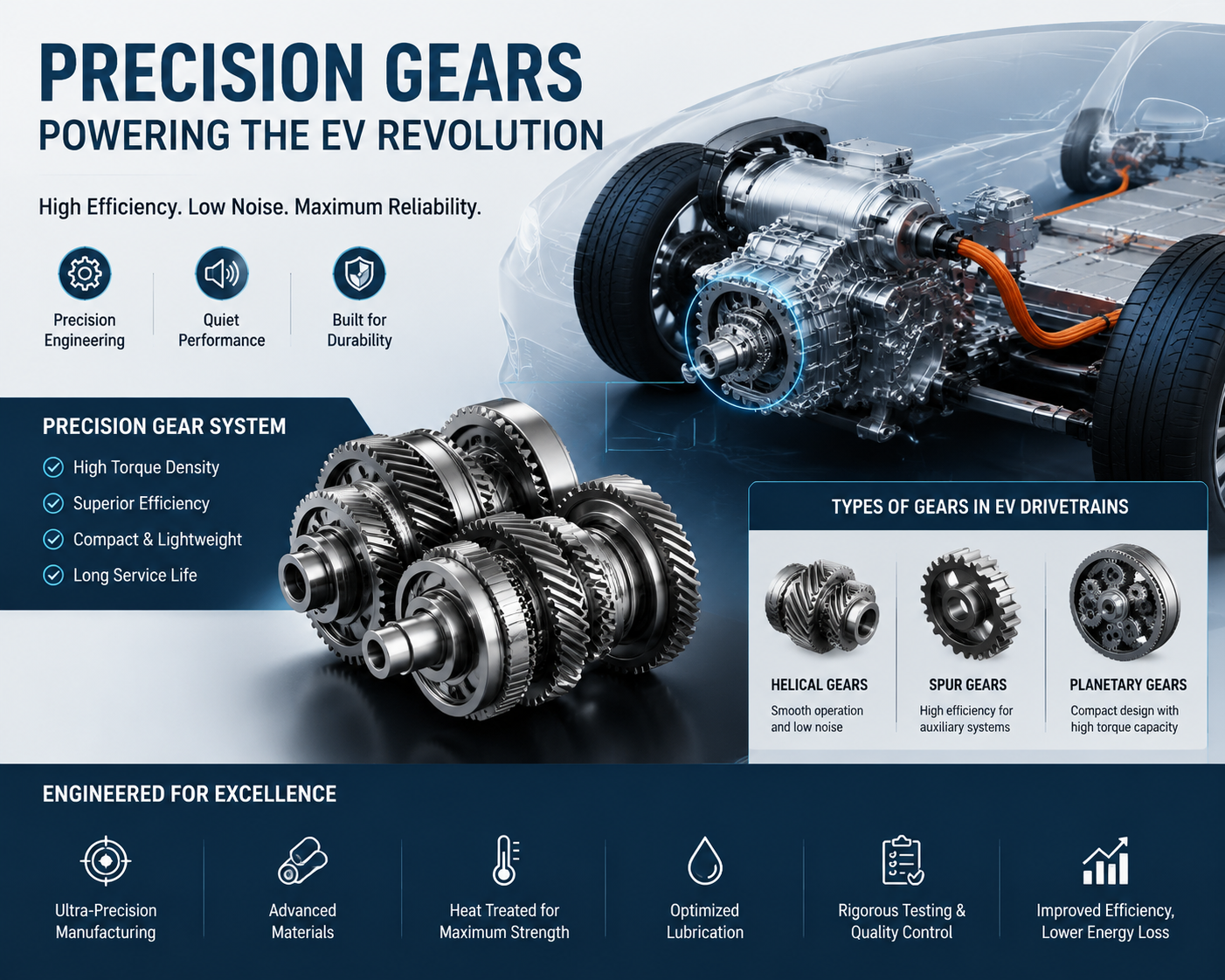
Electric vehicle reduction gear high torque spikes
EV reduction gears live in a world of extreme torque spikes—the permanent magnet motor can dump its full 400 Nm to the gearbox input in less than 50 milliseconds from a standing start, creating a shock load that would strip teeth off conventional designs. Engineers use wide‑faced helical gears with large pressure angles (22.5°), extremely tight backlash control (under 0.05 mm), and special anti‑shimmy bearing preload schemes. Because EVs are silent, gears are lapped or ground to a mirror finish (Ra 0.1 micron) and often coated with anti‑wear friction modifiers to eliminate gear whine.
Heavy construction machinery swing drives
A 50‑ton excavator’s swing drive rotates the entire upper structure against dig force, producing output torque around 80,000 Nm from a compact planetary gearbox mounted inside the swing bearing. The winning formula is three‑stage planetary with four planets per stage, running in high‑viscosity grease rather than oil to prevent leaks in vertical orientation. Sun gears are made from premium AISI 9310 vacuum‑melted steel, ring gears from nitrided 4140, and every unit is tested to 150% of rated torque before leaving the factory.
15. Cost vs Torque Capacity Analysis
Initial gear cost per Nm of torque rating
From a procurement perspective, calculate cost per Nm of torque capacity to separate bargains from false economies. Spur gears give the lowest cost per Nm—perhaps $0.50‑$1.50 per Nm—but only up to about 2,000 Nm. Helical gears run $1.50‑$4.00 per Nm but handle orders of magnitude more torque. Planetary systems, despite higher absolute cost ($5‑$15 per Nm), become cheaper per Nm at extreme torque levels because of their compact, multi‑load‑path efficiency. The real curve bends at AGMA Q10 and above, where grinding adds 30% to cost but doubles or triples torque capacity.
Maintenance intervals for different gear types
Total cost of ownership cannot ignore maintenance. A gear that costs half as much upfront but requires oil changes every 1,000 hours and a rebuild every 5,000 hours will quickly exceed the lifetime cost of a premium gear that runs 20,000 hours between services. Planetary systems often achieve 50,000 hours of bearing life and 100,000 hours of gear life when properly lubricated. Worm gears may need bronze wheel replacement every 10,000 hours under continuous high torque. When evaluating quotes, ask for recommended maintenance schedules and repair kit costs.
Total cost of ownership for high torque applications
A realistic TCO includes initial price, installation labor, lubricant and filters over life, scheduled maintenance, downtime cost for inspections and repairs, and probability‑weighted cost of catastrophic failure. Example: a $10,000 helical gearbox with 98% efficiency and 50,000‑hour life has a TCO of perhaps $25,000 including electricity and two oil changes; a $6,000 worm gear with 50% efficiency and 15,000‑hour life has a TCO exceeding $60,000 due to power waste and three rebuilds. Always demand an efficiency guarantee and a life prediction based on your exact duty cycle.
16. Procurement Checklist for High Torque Gears
Required design inputs: torque, speed, duty cycle
Before sending an RFQ, prepare a complete duty profile: nominal torque, maximum peak torque (with duration), number of starts and stops per hour, shock loads, ambient temperature range, required service life in hours, input speed range, whether reverse torque will occur, and mounting orientation (horizontal, vertical, or tilted). Provide all this data in a clear technical specification sheet and require the supplier to sign off on each line item—hand‑waving leads to mismatched expectations and failure.
Verification of supplier testing and certification
Do not accept a generic certificate of conformance as proof of quality. Require a certified material test report for gear steel (chemistry, hardenability, grain size), heat treatment furnace chart, surface hardness traverse from case to core, and magnetic particle inspection after grinding. For the assembled gearbox, demand a no‑load run‑in test of at least two hours followed by full‑load torque testing on a dynamometer until thermal equilibrium, with vibration and temperature recordings. Ask for raw data—if the supplier hesitates, they are hiding something.
Warranty clauses for torque-related failures
Your purchase agreement must include warranty language covering torque‑related failure modes—tooth bending fatigue, pitting, scuffing, bearing failure—for a period commensurate with expected life (typically 24‑60 months). The warranty should be voided only by documented abuse, over‑torque events, or improper lubrication. Specify that the supplier covers not just gearbox repair but also removal, reinstallation, freight, and a daily penalty for downtime beyond a certain period. Finally, require an independent root cause analysis for any warranty failure, at the supplier’s cost if the failure is their fault—this alone will dramatically improve quality control.
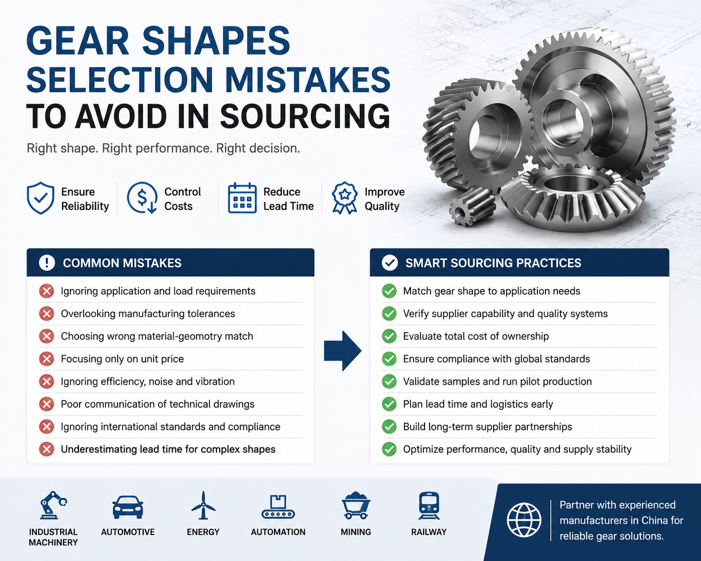
17. Common Specification Mistakes to Avoid
Overlooking start-up torque spikes
One of the most costly mistakes is assuming running torque tells the whole story while ignoring massive inrush torque required to accelerate from a dead stop—especially with high‑inertia loads like flywheels, large fans, or reciprocating compressors. Starting torque can easily be two to three times the nameplate rating. If you size for running torque alone, start‑up spikes will repeatedly overload teeth, causing low‑cycle fatigue that fails gears in hundreds rather than thousands of cycles. Always request locked rotor torque or breakaway torque and apply a safety factor of at least 1.8 for frequent starts.
Ignoring reverse torque requirements
Many engineers design for forward torque only to discover that their gearbox rattles under reverse torque—a particular problem for conveyors with backdriving from gravity, wind turbines with reversing gusts, or any system with overhauling loads. Reverse torque often has different load distribution because teeth contact on the opposite flank, which may have a different surface finish or residual stress state. Unless you explicitly specify bidirectional torque and require the gear to be fully symmetric (or tested in both directions), you may get a gear that works beautifully forward but whines, overheats, or fails when asked to reverse.
Misapplying safety factors for intermittent loads
Safety factors are not one‑size‑fits‑all. A gearbox in a candy wrapping machine running eight hours a day at smooth, steady torque might be fine with a 1.25 factor on bending stress, but the same gearbox in a rock crusher seeing shock loads every second would need a 2.0 factor or higher. Use the AGMA service factor classification based on prime mover type (electric motor, diesel engine, hydraulic motor) and driven machine shock characteristics (uniform, moderate, heavy shock), then multiply by an application‑specific reliability factor. When in doubt, go higher—the cost of a slightly oversized gearbox is negligible compared to the cost of an undersized failure.
18. Future Trends in High Torque Gear Design
Additive manufacturing for custom tooth profiles
The quiet revolution in gear manufacturing is additive—3D printing of near‑net tooth forms using laser powder bed fusion of tool steels or nickel‑based superalloys. This allows tooth profiles impossible with conventional hobbing or grinding, such as asymmetric pressure angles, internal cooling channels running through the tooth body, or graded porosity that damps vibration without sacrificing strength. While current additive gear technology is limited to smaller sizes (under 300 mm diameter), the ability to produce custom high torque gears with lead times of days rather than weeks and without expensive tooling will fundamentally change procurement, especially for low‑volume, high‑performance applications like racing transmissions or specialized industrial machinery.
Composite materials for weight reduction
Steel has been the king of high torque gears for centuries, but advanced composites—carbon fiber reinforced polymer with ceramic or metallic wear‑resistant surfaces—are beginning to challenge that dominance in aerospace actuators, electric vehicle drives, and portable heavy equipment. A composite gear can weigh 70% less than steel while offering comparable bending strength and much higher damping. The current limitations are low thermal conductivity (heat builds up quickly) and attaching composite gears to steel shafts, but as manufacturing techniques improve, expect hybrid composite‑steel high torque gears within five to ten years.
Smart gears with embedded torque sensing
The future is data: embedding thin‑film strain gauges, magnetoelastic sensors, or fiber Bragg gratings directly into gear tooth roots allows real‑time measurement of actual torque at each tooth, providing predictive maintenance data far superior to external vibration sensors. Imagine a gearbox that tells you, tooth by tooth, when load distribution is uneven, when a crack is initiating, or when lubrication is failing, all transmitted wirelessly without any external wiring or slip rings. A few premium gearbox manufacturers already offer such smart gears for wind turbines and mining equipment, and as sensor costs drop and power harvesting from gear vibration becomes viable, smart high torque gears will become standard, moving procurement from reactive replacement to truly predictive maintenance.