Table of Contents
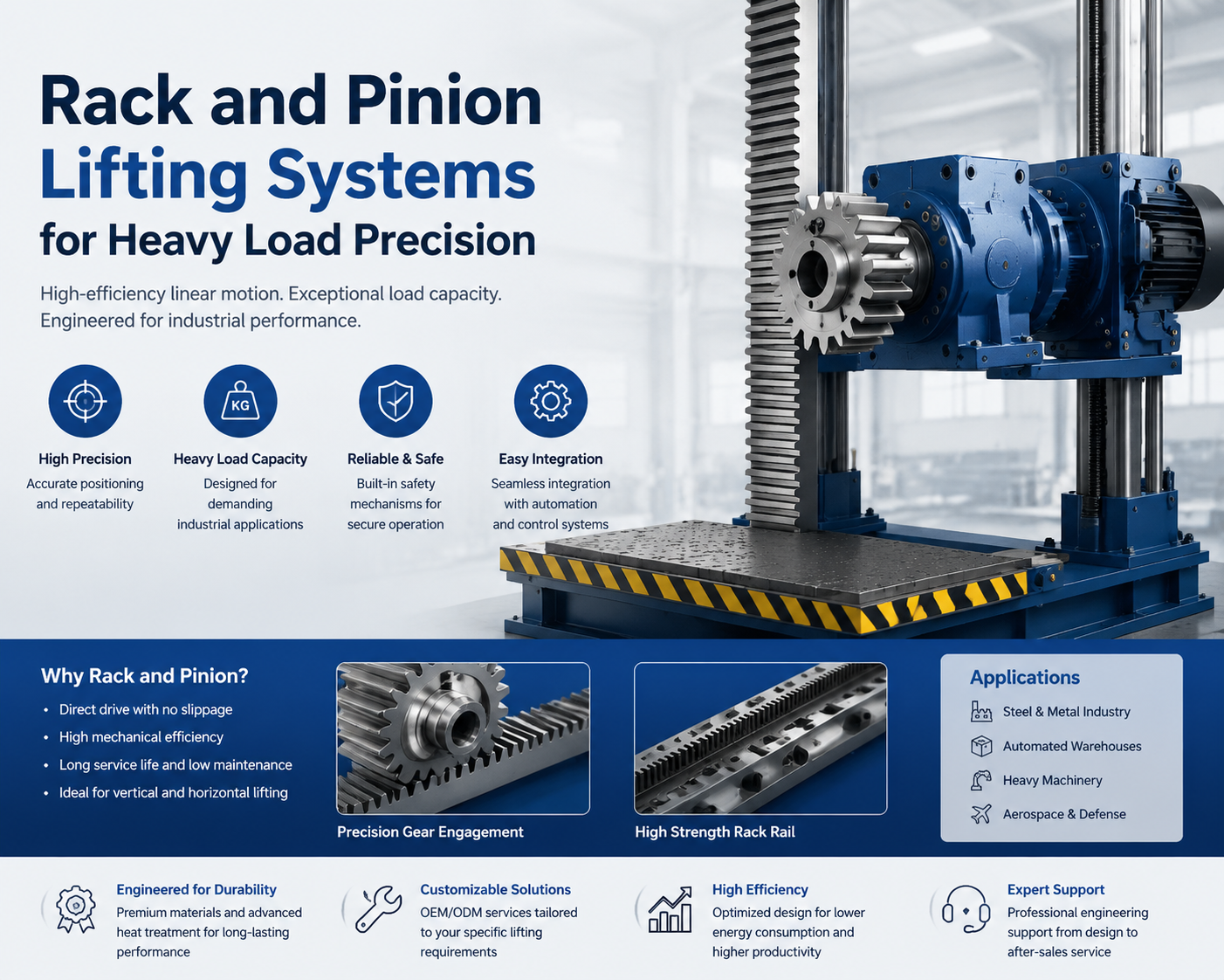
Rack and Pinion Lifting Systems for Heavy Load Precision
1. Introduction to Rack and Pinion Lifting Systems
1.1 Definition of rack and pinion lifting mechanism
A rack and pinion lifting mechanism is a deterministic linear actuation system where a rotating pinion gear engages a linear toothed rack to produce controlled vertical or horizontal displacement. From an engineering standpoint, it is a positive-drive conversion system, meaning motion is transmitted through direct tooth engagement rather than frictional or fluid-mediated forces. This eliminates slippage phenomena common in belt or hydraulic systems and ensures that every degree of rotation corresponds to a predictable linear travel distance.
In heavy industrial usage, the system is typically integrated with rigid guide structures, servo or induction motor drives, and reduction gearboxes, forming a high-load electromechanical lifting architecture. Procurement engineers often value this system because it simplifies motion control architecture while maintaining high structural rigidity under load.
1.2 Why precision lifting matters in heavy load industries
Precision lifting is not simply about achieving fine positioning; it is fundamentally about maintaining structural alignment integrity during multi-ton load transfers. When a steel slab, mold assembly, or machine base is lifted even slightly off-axis, internal stress redistribution can cause deformation, bolt shear misalignment, or downstream assembly errors.
In modern manufacturing environments where tolerances are tightening into sub-millimeter domains, lifting accuracy directly affects production yield. The rack and pinion system ensures repeatable vertical positioning without drift, creep, or hydraulic compressibility effects.
1.3 Key industries relying on rack and pinion systems
Rack and pinion lifting systems are widely deployed in steel manufacturing plants, automotive assembly lines, aerospace tooling stations, port cargo handling equipment, and automated warehouse elevators. In steel mills, they are used for slab positioning under extreme thermal and mechanical loads.
In shipbuilding and heavy machinery fabrication, these systems provide synchronized lifting of large structural sections. Procurement professionals favor them because they offer long lifecycle durability compared to hydraulic alternatives.
2. Core Working Principle of Rack and Pinion Lifting
2.1 Interaction between rack gear and pinion gear
The fundamental operation relies on involute gear tooth engagement between a rotating pinion and a stationary rack. The pinion acts as the driving element, transferring tangential force into linear motion.
This interaction is a controlled rolling-sliding hybrid contact. Proper systems maintain optimal contact ratio greater than 1.2 ensuring multi-tooth engagement.
Reference: Rack and Pinion System
2.2 Conversion of rotational motion to linear motion
Linear displacement equals π × pitch diameter per rotation, making motion deterministic and predictable. This is why rack and pinion systems are widely used in precision automation.
Unlike hydraulic systems, this mechanism avoids compressibility errors and maintains geometric consistency in closed-loop control systems.
2.3 Load transfer mechanics under heavy-duty conditions
Load transfer occurs across multiple teeth under Hertzian contact stress conditions. Stress distribution is influenced by material elasticity and microgeometry accuracy.
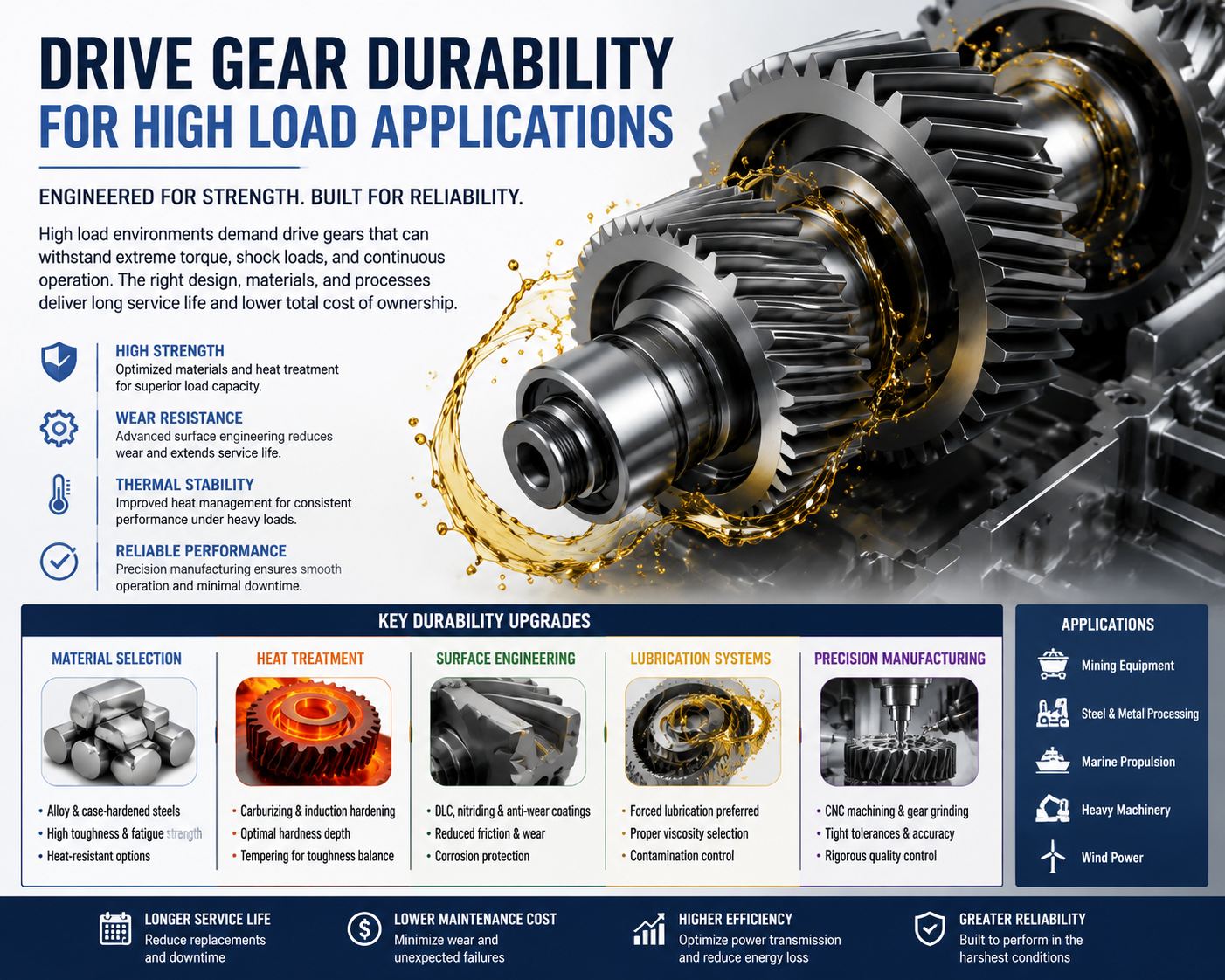
Surface treatments such as carburizing improve fatigue resistance while maintaining core toughness.
3. Structural Components of the System
3.1 Rack rail design and material selection
Rack rails are typically made from alloy steels such as 42CrMo, selected for toughness and hardenability. Precision grinding ensures geometric accuracy.
3.2 Pinion gear geometry and tooth profile
Pinion gears use involute geometry ensuring constant velocity ratio and smooth transmission.
Reference: Involute Gear Geometry
3.3 Motor, gearbox, and drive integration
Servo motors or induction motors paired with planetary gearboxes provide torque-speed optimization. Encoder feedback ensures closed-loop precision control.
4. Load Capacity Considerations for Heavy Applications
4.1 Static vs dynamic load behavior
Static load is gravitational force at rest, while dynamic load includes acceleration effects increasing stress by up to 50%.
4.2 Stress distribution across gear teeth
Stress analysis often uses Finite Element Method simulations to evaluate tooth deformation and load paths.
Reference: Finite Element Analysis
4.3 Safety factors in industrial lifting design
Safety factors between 1.5 and 3.0 are applied depending on application criticality to ensure operational reliability.
5. Precision Control in Lifting Operations
5.1 Positioning accuracy in linear motion systems
Servo-controlled rack and pinion systems achieve sub-millimeter precision depending on system rigidity.
5.2 Role of servo motors and encoders
Encoders provide real-time feedback ensuring closed-loop correction of positional errors.
5.3 Backlash reduction techniques
Preloaded pinion systems and precision-ground gears eliminate mechanical play during direction changes.
6. Advantages Over Traditional Lifting Systems
6.1 Comparison with hydraulic lifting systems
Hydraulic systems suffer from compressibility and viscosity variation, while rack and pinion systems remain mechanically rigid.
6.2 Advantages over chain and cable hoists
Chain systems experience elongation and wear, whereas rack and pinion maintain geometric consistency.
6.3 Long-term operational stability benefits
Rack and pinion systems maintain calibration stability over long cycles reducing downtime and maintenance cost.
7. Design Parameters for Heavy Load Performance
7.1 Module size and gear ratio selection
Larger module sizes increase load capacity but reduce smoothness and increase inertia.
7.2 Material hardness and heat treatment processes
Carburizing and induction hardening produce surface hardness up to HRC 58–62 with tough core structure.
7.3 Alignment tolerances and installation precision
Laser alignment ensures proper rack engagement and prevents uneven tooth loading.
8. Industrial Applications Overview
8.1 Steel manufacturing and rolling mills
Used in slab handling systems under extreme heat and load conditions requiring high reliability.
8.2 Automated warehouses and logistics systems
Vertical lift modules rely on rack and pinion systems for high-speed repetitive lifting operations.
8.3 Heavy machinery assembly lines
Used for precise positioning of multi-ton components before welding and assembly.
9. Safety Mechanisms in Rack and Pinion Systems
9.1 Anti-fall and locking devices
Mechanical locking systems prevent uncontrolled descent during power failure.
9.2 Overload protection systems
Load sensors and torque monitoring prevent structural overload conditions.
9.3 Emergency stop and fail-safe design
Fail-safe systems ensure safe mechanical state under electrical or system failure.
10. Efficiency and Energy Consumption Factors
10.1 Mechanical efficiency of gear engagement
Efficiency depends on lubrication, alignment, and tooth accuracy.
10.2 Motor load optimization strategies
VFD and servo systems adjust torque output dynamically for efficiency.
10.3 Energy recovery in vertical lifting systems
Regenerative braking recovers energy during downward motion cycles.
11. Maintenance Requirements and Lifecycle Management
11.1 Lubrication strategies for gear longevity
Proper lubrication reduces friction and extends system lifespan.
11.2 Wear inspection and predictive maintenance
Vibration analysis detects early-stage wear conditions.
11.3 Replacement cycles and spare part planning
Lifecycle planning ensures spare availability to reduce downtime.
12. Common Failure Modes and Troubleshooting
12.1 Tooth wear and pitting issues
Pitting results from fatigue and poor lubrication conditions.
12.2 Misalignment and vibration problems
Misalignment causes uneven load distribution and vibration.
12.3 Motor overload and thermal failures
Overload leads to overheating and insulation breakdown.
13. Material Selection for Heavy Duty Durability
13.1 Alloy steel and case-hardened materials
Material selection defines the structural survival boundary of rack and pinion lifting systems. High-performance systems rely on alloy steels such as 42CrMo4, 20MnCr5, and similar grades engineered for high fatigue resistance and impact toughness.
The design philosophy is a dual-property system: a hardened outer surface to resist wear and pitting, and a ductile core to absorb shock loading without brittle fracture. This is achieved through carburizing or carbonitriding processes that create a hardened case layer while preserving internal toughness.
In industrial reality, this combination is what prevents catastrophic gear tooth failure under sudden load spikes, especially in steel mills and heavy automation environments.
13.2 Corrosion resistance in harsh environments
Corrosion is a silent degradation mechanism that reduces effective load-bearing cross-section over time. In rack and pinion systems, this directly accelerates fatigue and reduces service life.
Protection strategies include phosphate coatings, zinc plating, black oxide treatment, and specialized epoxy coatings. In extreme environments such as marine ports or chemical plants, stainless alloys or nickel-based coatings may be used.
The engineering trade-off is always between hardness and corrosion resistance—overly soft coatings wear quickly, while overly hard coatings may crack under impact loading.
13.3 Composite and advanced material innovations
Advanced composites and hybrid materials are gradually entering secondary structural applications. Fiber-reinforced polymers and metal matrix composites offer reduced weight and improved vibration damping characteristics.
However, due to load concentration requirements, primary rack elements still rely on steel-based alloys. Composites are mainly used in housings, damping structures, or non-load-critical components.
14. Manufacturing Standards and Quality Control
14.1 ISO and DIN gear manufacturing standards
Gear systems are governed by ISO 1328 and DIN 3962 standards, which define accuracy grades, pitch deviation limits, and surface quality requirements.
These standards ensure interchangeability and predictable performance across global supply chains. Higher precision grades reduce vibration, improve load distribution, and extend operational lifespan.
14.2 Precision machining and inspection methods
Manufacturing processes include CNC hobbing, gear shaping, and precision grinding after heat treatment. Post-heat-treatment correction is essential due to thermal distortion effects.
Inspection technologies such as CMM (Coordinate Measuring Machines), gear analyzers, and surface profilometers ensure micron-level accuracy verification.
14.3 OEM/ODM quality assurance processes
OEM/ODM production requires multi-stage quality control including material verification, in-process inspection, and final performance validation.
Tests include hardness checks, load simulation, fatigue testing, and dimensional verification to ensure consistent batch performance.
15. Integration with Automation and Smart Systems
15.1 PLC and industrial control system integration
Modern rack and pinion lifting systems are integrated into PLC-based automation architectures, enabling synchronized control with conveyors, robots, and safety systems.
This integration allows multi-axis coordination, interlock logic, and real-time operational control across entire production lines.
15.2 Sensor feedback for real-time positioning
Linear encoders, load cells, and proximity sensors provide continuous feedback for position, speed, and force monitoring.
This transforms the system from a passive mechanical device into a closed-loop intelligent motion platform capable of real-time correction.
15.3 Industry 4.0 and predictive analytics adoption
Industry 4.0 introduces data-driven monitoring where vibration, temperature, and torque data are continuously analyzed.
Predictive analytics enables early fault detection, reducing unplanned downtime and improving lifecycle efficiency across industrial systems.
16. Cost Factors in Procurement Decisions
16.1 Initial investment vs lifecycle cost
Initial cost represents only a fraction of total ownership expenses. Lifecycle cost includes maintenance, downtime, energy usage, and replacement cycles.
Low-cost systems often result in higher long-term expenses due to increased wear rates and reduced efficiency under load.
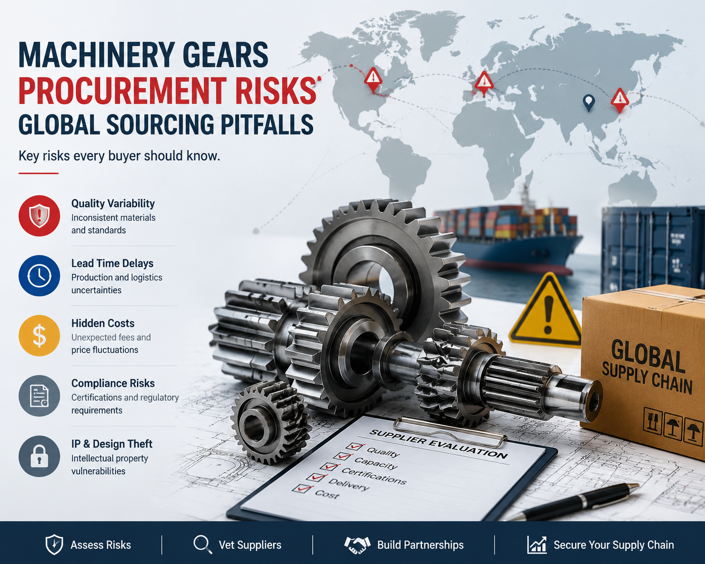
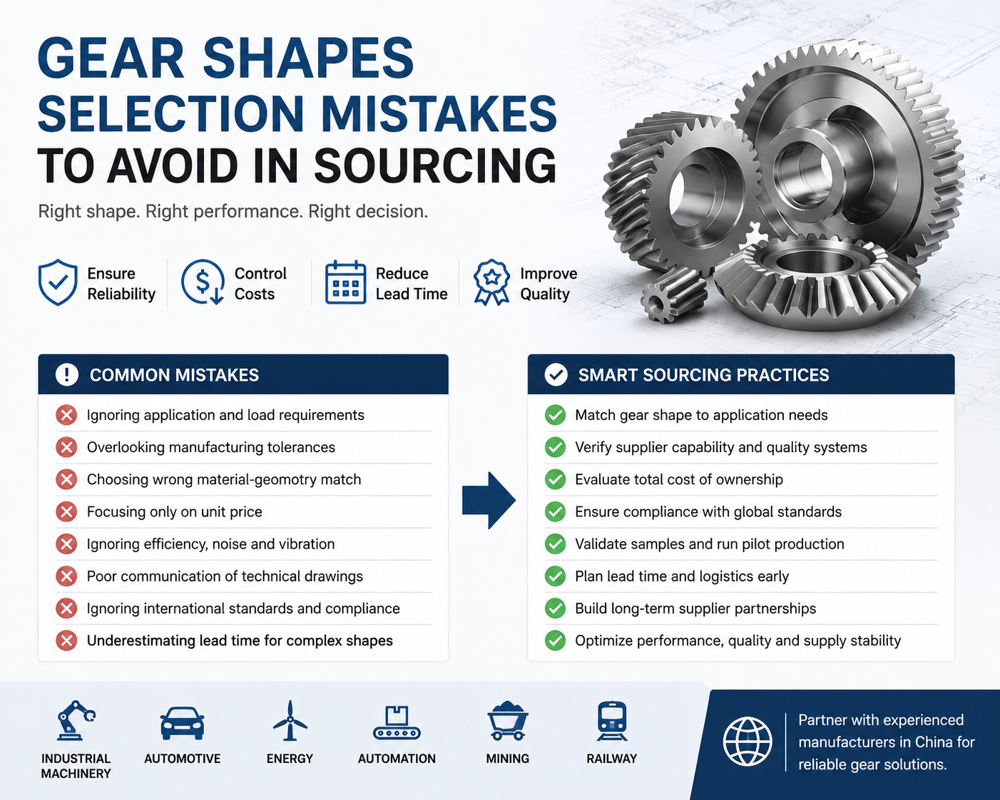
16.2 Supplier evaluation and OEM sourcing strategy
Supplier evaluation includes production capability, quality consistency, engineering support, and delivery reliability.
OEM sourcing strategies prioritize long-term partnership stability over short-term price reduction, ensuring predictable system performance.
16.3 Total cost of ownership optimization
Total Cost of Ownership (TCO) integrates all operational expenses across system lifecycle.
Optimization focuses on improving efficiency, reducing maintenance frequency, and minimizing downtime risks for maximum economic performance.
17. Installation Best Practices for Industrial Systems
17.1 Foundation and structural support requirements
A rigid and vibration-free foundation is essential for maintaining geometric stability of rack and pinion alignment.
Any foundation deformation directly translates into gear misalignment and accelerated wear, making structural rigidity a critical installation parameter.
17.2 Alignment and calibration procedures
Laser alignment systems and precision measurement tools ensure correct rack-to-pinion engagement geometry during installation.
Multi-segment rack installations require careful calibration to prevent cumulative pitch errors and vibration issues.
17.3 On-site testing and commissioning steps
Commissioning includes no-load testing, staged load testing, and dynamic operational validation under real working conditions.
Key performance parameters such as vibration, motor current, and positioning accuracy are verified before production deployment.
18. Future Trends in Rack and Pinion Lifting Technology
18.1 Smart servo-driven lifting systems
Next-generation systems incorporate adaptive servo control algorithms that adjust torque and motion profiles dynamically based on load conditions.
This results in self-optimizing systems capable of improving efficiency and reducing mechanical stress over time.
18.2 Lightweight high-strength material adoption
Advancements in metallurgy are enabling stronger yet lighter alloys that reduce inertia while maintaining load capacity.
This improves energy efficiency and enables faster cycle times in automated industrial systems.
18.3 AI-driven maintenance and optimization systems
Artificial intelligence systems analyze operational data to predict wear and maintenance needs before failure occurs.
This shift from reactive to predictive maintenance significantly improves uptime and reduces lifecycle costs in industrial operations.