Common Worm Gear Reducer Faults and Repair Methods
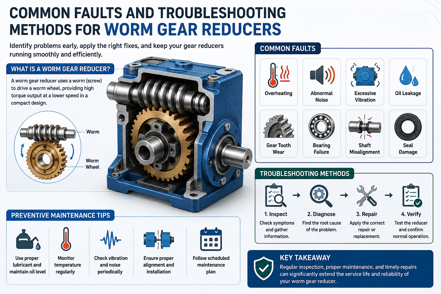
Common Faults and Troubleshooting Methods for Worm Gear Reducers
Worm gear reducers play a critical role in industrial power transmission systems because they provide reliable torque multiplication, smooth speed reduction, and exceptional compactness for demanding mechanical applications. In manufacturing plants, mining facilities, food processing lines, conveyor assemblies, and automated production environments, these reducers often operate continuously under heavy load conditions where durability and stability are absolutely indispensable.
However, even the most robust worm gear reducer can experience overheating, vibration, lubrication degradation, bearing damage, shaft misalignment, and efficiency loss when subjected to prolonged operational stress or improper maintenance practices. Understanding these faults and implementing systematic troubleshooting methods allows maintenance engineers and purchasing specialists to reduce downtime, extend equipment service life, and optimize overall operational efficiency.
1. Introduction to Worm Gear Reducers
1.1 Definition and Working Principle of Worm Gear Reducers
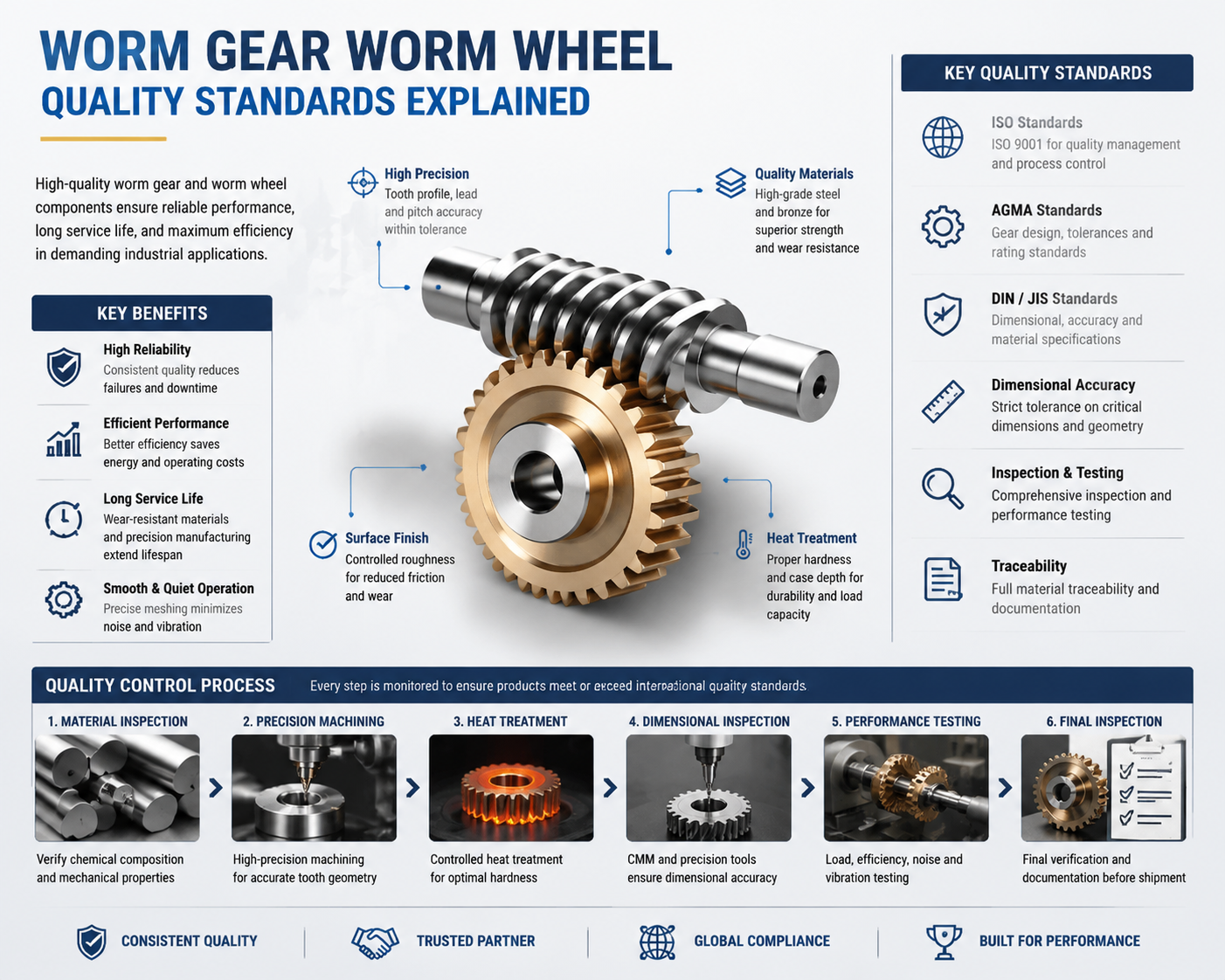
A worm gear reducer is a mechanical transmission device designed to reduce rotational speed while increasing torque output through the interaction of a worm shaft and worm wheel. The worm resembles a threaded screw, while the worm wheel functions similarly to a conventional gear. During operation, the worm shaft drives the worm wheel through sliding contact, enabling substantial speed reduction within a compact mechanical configuration.
Unlike spur or helical gears that rely primarily on rolling contact, worm gear reducers operate through controlled sliding friction, which contributes to smoother motion and quieter operation. This unique configuration also allows certain worm gear systems to possess self-locking capabilities, preventing reverse motion in lifting and positioning applications.
1.2 Importance of Worm Gear Reducers in Industrial Applications
Worm gear reducers are widely utilized because they provide stable torque transmission, compact installation dimensions, and dependable operation under fluctuating load conditions. Their ability to achieve high reduction ratios in a single stage makes them highly suitable for conveyors, packaging systems, industrial mixers, and heavy-duty machinery.
From a procurement standpoint, worm gear reducers are often considered cost-effective solutions compared with more sophisticated planetary systems. Maintenance engineers frequently appreciate their structural simplicity and reliable operational behavior, particularly in environments where downtime can cost an arm and a leg.
1.3 Common Industries That Use Worm Gear Systems
Worm gear reducers are extensively used in industries such as mining, food processing, agriculture, textile manufacturing, logistics automation, wastewater treatment, and material handling. In mining and cement production, reducers must withstand extreme dust contamination and continuous operational stress.
Food-grade facilities commonly use corrosion-resistant worm reducers with specialized lubricants to satisfy hygiene regulations. Meanwhile, automated warehouse systems depend on worm gear assemblies for precise positioning and stable low-speed torque output.
2. Main Components of a Worm Gear Reducer
2.1 Worm Shaft Structure and Function
The worm shaft serves as the primary driving component within the reducer assembly. Typically manufactured from hardened alloy steel, the shaft contains precision-machined helical threads designed to mesh smoothly with the worm wheel.
The dimensional accuracy and surface finish of the worm shaft significantly influence transmission efficiency, heat generation, and operational noise levels. Even slight geometric inconsistencies can create uneven contact stress and accelerate wear patterns over time.
2.2 Worm Wheel Design and Material Selection
The worm wheel is generally fabricated from phosphor bronze or other anti-friction copper alloys because these materials provide excellent resistance to galling and adhesive wear. The combination of a hardened steel worm and bronze wheel creates favorable tribological characteristics during sliding contact.
Material selection involves balancing durability, efficiency, thermal conductivity, and procurement cost. Premium bronze alloys often deliver superior longevity in demanding industrial environments.
2.3 Bearings, Housing, and Lubrication System
Bearings support radial and axial loads generated during operation while maintaining precise shaft alignment. Tapered roller bearings are frequently selected because worm gear systems produce significant thrust forces.
The housing protects internal components against contamination and mechanical impact. Cast iron housings remain popular due to their rigidity and vibration damping properties. Meanwhile, the lubrication system plays a vital role in reducing friction, dissipating heat, and extending service life.
3. Typical Operating Conditions of Worm Gear Reducers
3.1 Load Requirements and Torque Transmission
Worm gear reducers are engineered to handle substantial torque loads at relatively low operating speeds. Proper load distribution is essential because excessive loading creates elevated stress concentrations on gear teeth and bearings.
Shock loading conditions caused by abrupt starts and stops can severely shorten reducer lifespan. Continuous overload operation frequently results in premature fatigue failure.
3.2 Speed Reduction and Efficiency Factors
One of the primary advantages of worm gear systems is their ability to achieve high reduction ratios within a single stage. However, efficiency losses occur due to sliding friction between the worm and wheel surfaces.
Efficiency depends on lubrication quality, operating temperature, gear geometry, and reduction ratio. Higher reduction ratios generally produce more heat because frictional losses increase substantially.
3.3 Environmental Influences on Reducer Performance
Environmental conditions can dramatically affect reducer reliability and durability. Excessive humidity, airborne particulates, corrosive chemicals, and temperature extremes accelerate component deterioration.
In mining facilities and steel plants, dust contamination frequently infiltrates seals and contaminates lubricants, creating abrasive conditions inside the gearbox.
4. Common Causes of Worm Gear Reducer Failures
4.1 Improper Installation Practices
Improper installation is one of the most common causes of premature reducer failure. Shaft misalignment, inadequate mounting support, and incorrect bolt torque can create abnormal stress conditions immediately after commissioning.
Rushed installations often lead to expensive downtime later because even minor alignment errors may cause catastrophic bearing or gear damage over time.
4.2 Inadequate Lubrication and Oil Contamination
Lubrication failure represents a major contributor to reducer breakdown. Low oil levels, contaminated lubricants, or improper viscosity selection compromise the protective oil film separating contacting surfaces.
Once metal-to-metal contact begins, friction and heat generation escalate rapidly, causing severe surface scoring and accelerated wear.
4.3 Excessive Load and Operational Stress
Operating beyond rated load capacity subjects internal components to excessive stress and thermal loading. Overloading commonly leads to gear tooth deformation, bearing fatigue, and shaft deflection.
Maintenance personnel often describe overloaded reducers as “working themselves into the ground,” which accurately reflects the progressive mechanical deterioration that occurs under extreme stress conditions.
5. Overheating Problems in Worm Gear Reducers
5.1 Symptoms of Overheating During Operation
Common overheating symptoms include elevated housing temperatures, burnt oil odor, lubricant discoloration, excessive noise, and reduced operational efficiency.
Thermal expansion caused by overheating can alter internal clearances and further increase friction, creating a damaging cycle of rising temperatures.
5.2 Causes of High Temperature in Gear Reducers
Excessive friction, poor lubrication, overload conditions, and inadequate ventilation are among the leading causes of overheating. High ambient temperatures further reduce cooling effectiveness.
Improper lubricant viscosity can also contribute significantly to thermal instability within the gearbox.
5.3 Effective Cooling and Repair Methods
Cooling solutions include external cooling fans, oil circulation systems, and heat exchangers. Reducing operational load and improving airflow can substantially lower operating temperatures.
Repair procedures often involve replacing damaged bearings, correcting alignment issues, and flushing degraded lubricant from the system.
6. Abnormal Noise Issues in Worm Gear Reducers
6.1 Identifying Different Types of Mechanical Noise
Mechanical noise can reveal valuable diagnostic information regarding internal gearbox conditions. Grinding noises frequently indicate severe gear wear, while rhythmic knocking often suggests bearing damage.
Whining sounds are commonly associated with improper gear meshing or lubrication deficiencies.
6.2 Causes of Noise from Gear Misalignment or Wear
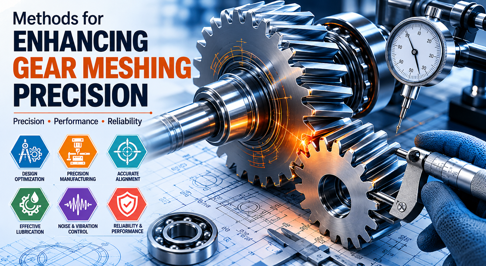
Gear misalignment alters contact patterns between mating surfaces, causing uneven stress distribution and abnormal vibration. Surface pitting and excessive backlash frequently increase operational noise levels.
6.3 Troubleshooting and Noise Reduction Solutions
Corrective measures include shaft realignment, bearing replacement, lubrication optimization, and foundation reinforcement. Advanced vibration monitoring systems can help identify faults before catastrophic failure occurs.
7. Vibration Problems and Diagnostic Methods
7.1 Common Sources of Excessive Vibration
Common vibration sources include rotating imbalance, loose mounting hardware, bearing defects, coupling misalignment, and gear damage.
7.2 Inspection Techniques for Vibration Analysis
Vibration analyzers, thermal imaging systems, and frequency spectrum analysis are widely used for diagnosing gearbox abnormalities.
7.3 Repair Methods for Stabilizing the Reducer
Balancing rotating components, tightening structural fasteners, and replacing defective bearings significantly reduce vibration intensity.
8. Lubrication Failures and Oil Leakage
8.1 Signs of Lubrication Deficiency
Increased temperature, metallic debris in oil, foam formation, and elevated operating noise are common indicators of lubrication problems.
8.2 Common Reasons for Oil Leakage
Damaged seals, excessive internal pressure, worn shafts, and gasket failure commonly cause oil leakage in worm gear reducers.
8.3 Proper Lubricant Selection and Maintenance
Choosing the correct lubricant viscosity and additive package is essential for maintaining operational stability and minimizing wear.
9. Gear Tooth Wear and Surface Damage
9.1 Types of Gear Tooth Wear
Common gear tooth wear patterns include pitting, scoring, abrasive wear, and adhesive galling.
9.2 Factors Leading to Premature Gear Damage
Poor lubrication, contamination, overload conditions, and improper heat treatment significantly accelerate gear deterioration.
9.3 Repair and Replacement Techniques for Worn Gears
Minor surface damage may be corrected through polishing or grinding, while severe deterioration requires complete gear replacement.
10. Bearing Failures in Worm Gear Reducers
10.1 Early Warning Signs of Bearing Damage
Excessive noise, abnormal vibration, and elevated temperatures are common warning signs of bearing failure.
10.2 Causes of Bearing Overload and Fatigue
Improper lubrication, contamination, overload conditions, and shaft misalignment commonly reduce bearing lifespan.
10.3 Bearing Replacement and Preventive Measures
Using proper installation tools and maintaining clean lubrication conditions significantly improve bearing reliability.
11. Shaft Misalignment and Mechanical Deformation
11.1 Causes of Shaft Misalignment
Improper installation, thermal distortion, and foundation settlement are frequent causes of shaft misalignment.
11.2 Effects of Deformation on Gear Performance
Misalignment increases stress concentration, accelerates wear, and reduces transmission efficiency.
11.3 Alignment Correction and Repair Procedures
Laser alignment tools provide highly accurate shaft positioning and help minimize mechanical stress.
12. Seal Damage and Leakage Troubleshooting
12.1 Common Types of Seal Failures
Seal hardening, cracking, and lip wear frequently occur due to prolonged heat exposure and contamination.
12.2 Environmental and Mechanical Causes of Leakage
Dust infiltration, chemical exposure, and shaft surface imperfections commonly compromise seal performance.
12.3 Seal Replacement and Preventive Maintenance
Routine inspection and timely replacement of damaged seals help prevent costly lubricant leakage.
13. Efficiency Loss in Worm Gear Reducers
13.1 Factors That Reduce Transmission Efficiency
Frictional losses, poor lubrication, excessive load, and gear wear significantly reduce reducer efficiency.
13.2 Impact of Friction and Heat Generation
Heat buildup accelerates lubricant oxidation and increases energy consumption throughout the drive system.
13.3 Methods to Improve Operational Efficiency
Precision machining, synthetic lubricants, and proper alignment can greatly improve overall operational efficiency.
14. Electrical and Motor-Related Faults
14.1 Motor Overload and Starting Issues
Voltage instability and excessive startup torque frequently overload electric motors connected to worm reducers.
14.2 Connection Problems Between Motor and Reducer
Improper coupling alignment generates excessive vibration and mechanical stress.
14.3 Electrical Inspection and Troubleshooting Methods
Insulation resistance testing and current analysis help identify electrical abnormalities before serious damage occurs.
15. Preventive Maintenance Strategies for Worm Gear Reducers
15.1 Daily Inspection and Monitoring Procedures
Routine inspection should include temperature monitoring, vibration analysis, and lubricant level verification.
15.2 Scheduled Lubrication and Component Checks
Preventive lubrication schedules significantly reduce unexpected failures and extend gearbox lifespan.
15.3 Predictive Maintenance Using Condition Monitoring
Advanced monitoring technologies enable maintenance teams to detect developing faults before catastrophic breakdown occurs.
16. Step-by-Step Troubleshooting Process
16.1 Initial Fault Detection and Safety Precautions
Always isolate electrical power sources and follow lockout procedures before beginning inspection or repair work.
16.2 Systematic Inspection and Root Cause Analysis
A structured troubleshooting process helps maintenance teams identify root causes accurately and avoid unnecessary repairs.
16.3 Testing After Repair and Performance Verification
Operational testing ensures repaired reducers function correctly and comply with performance specifications.
17. Repair Methods for Extending Reducer Service Life
17.1 Reconditioning Damaged Gear Components
Surface refinishing and precision grinding can restore moderately damaged gear surfaces.
17.2 Replacing Critical Mechanical Parts
Replacing worn bearings, seals, and shafts prevents secondary failures and improves system reliability.
17.3 Upgrading Reducer Systems for Better Reliability
Modern lubrication systems and condition monitoring technologies improve long-term operational stability.
18. Choosing the Right Worm Gear Reducer for Applications
18.1 Load Capacity and Speed Selection Criteria
Reducer selection should consider torque requirements, operational speed, service factors, and duty cycles.
18.2 Material and Housing Considerations
Corrosion resistance, thermal stability, and structural rigidity are essential selection considerations.
18.3 Factors Purchasers Should Evaluate Before Buying
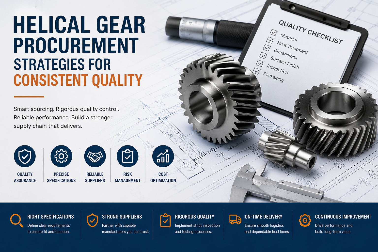
Purchasers should evaluate supplier reputation, maintenance accessibility, spare part availability, and lifecycle costs.
19. Safety Considerations During Reducer Maintenance
19.1 Lockout and Equipment Isolation Procedures
Proper lockout procedures eliminate accidental startup hazards during maintenance operations.
19.2 Safe Handling of Lubricants and Components
Technicians should wear protective equipment when handling industrial lubricants and heavy mechanical components.
19.3 Workplace Safety Standards for Repair Operations
Compliance with industrial safety regulations minimizes workplace injuries and operational hazards.
20. Future Trends in Worm Gear Reducer Technology
20.1 Smart Monitoring and IoT Integration
Modern worm gear reducers increasingly incorporate intelligent sensors for real-time condition monitoring and predictive maintenance.
20.2 Advanced Lubrication and Material Innovations
High-performance synthetic lubricants and advanced alloy materials continue improving reducer durability and efficiency.
20.3 Energy-Efficient Worm Gear Reducer Developments
Manufacturers are focusing on reducing frictional losses and enhancing energy efficiency through optimized gear geometry.
21. Conclusion
21.1 Summary of Common Worm Gear Reducer Faults
Common faults include overheating, vibration, lubrication failure, gear wear, shaft misalignment, and bearing damage.
21.2 Importance of Timely Troubleshooting and Repair
Timely troubleshooting minimizes downtime, reduces repair costs, and prevents catastrophic equipment failure.
21.3 Best Practices for Long-Term Reducer Reliability
Consistent maintenance, proper lubrication, accurate alignment, and predictive monitoring collectively ensure dependable long-term performance.