Comprehensive Guide to Gear Lubricant Selection
1. Introduction to Bevel Gears
1.1 Definition and Basic Concept of Bevel Gears
Bevel gears are specialized mechanical transmission components designed to transfer rotational motion and torque between intersecting shafts, most commonly arranged at a 90-degree angle. Unlike cylindrical gears that operate on parallel axes, bevel gears feature conically shaped pitch surfaces, allowing machinery designers to redirect power flow in compact and mechanically elegant configurations. In practical industrial environments, these gears act like the unsung utility players on a championship pickleball squad — maybe they do not grab the headlines, but they quietly keep the whole operation humming along.
The geometry of bevel gears enables smooth angular power transmission in systems where spatial limitations or directional changes make conventional spur gears impractical. Their tapered tooth architecture allows gradual meshing engagement, reducing abrupt impact forces while improving operational fluidity. Whether found inside automotive differentials, mining conveyors, marine propulsion systems, or robotic actuators, bevel gears remain indispensable in modern engineering ecosystems.
1.2 Importance in Industrial Machinery
Industrial machinery depends heavily on reliable torque transfer, and bevel gears deliver precisely that under demanding operating conditions. From steel rolling mills to agricultural harvesters, bevel gears facilitate directional motion changes while maintaining impressive mechanical efficiency. In heavy-duty systems where downtime costs real money and operators are already running around like their hair’s on fire, dependable gear performance becomes mission critical.
Bevel gears also contribute significantly to equipment miniaturization. Because they can redirect motion within constrained assemblies, engineers can develop more compact drivetrains without sacrificing performance. This design flexibility is especially beneficial in aerospace systems, automated manufacturing cells, and high-performance transportation platforms where every cubic inch matters.
1.3 Overview of Bevel Gear Design
Bevel gear design combines geometric precision, tribological science, and mechanical durability into one highly specialized discipline. Engineers must evaluate torque loads, rotational velocity, tooth contact patterns, lubrication conditions, thermal expansion behavior, and material hardness before finalizing a gearset design. It is not exactly a slap-it-together-and-send-it kind of process.
Successful bevel gear design focuses on optimizing tooth geometry, minimizing frictional losses, and extending service life under fluctuating load conditions. Modern computational software allows engineers to model contact stress distribution and predict dynamic performance with extraordinary precision, helping manufacturers produce gears capable of surviving brutal industrial workloads.
2. History and Evolution of Bevel Gears
2.1 Early Applications in Mechanical Systems
The origins of bevel gears trace back centuries to rudimentary milling machinery and primitive mechanical transfer systems. Early civilizations employed basic angular gear arrangements in water wheels, clockmaking assemblies, and agricultural devices. Though primitive by modern standards, these early implementations established the foundational principles of rotational redirection that still govern gear engineering today.
During the Industrial Revolution, bevel gears gained substantial prominence as factories demanded increasingly sophisticated mechanical systems. Steam-powered machinery required durable motion-transfer components capable of operating continuously under substantial stress, pushing machinists to refine gear-cutting methods and improve tooth accuracy.
2.2 Innovations in Bevel Gear Manufacturing
Manufacturing innovations transformed bevel gears from hand-crafted components into precision-engineered industrial assets. The development of dedicated gear generators, Gleason cutting systems, and CNC-controlled machining centers dramatically improved dimensional accuracy and production consistency.
Heat treatment advancements also revolutionized bevel gear durability. Processes such as carburizing, induction hardening, and nitriding enabled manufacturers to create exceptionally hard wear-resistant surfaces while preserving a ductile core structure capable of absorbing impact loads. That combination is the mechanical equivalent of having both a cannon arm and soft hands at the kitchen line.
2.3 Modern Industrial Relevance
Today, bevel gears occupy a central role in virtually every major industrial sector. Renewable energy systems, robotics, aerospace propulsion, and autonomous manufacturing platforms all depend on precision bevel gearing for reliable motion control. As automation expands globally, the demand for high-performance bevel gear assemblies continues climbing at a brisk pace.
Modern industries prioritize efficiency, reduced maintenance requirements, and lower operational noise, making advanced bevel gear technology more relevant than ever before.
3. Key Components of Bevel Gears
3.1 Gear Teeth and Pitch
The teeth of a bevel gear serve as the primary contact surfaces responsible for torque transfer. Tooth geometry directly influences load distribution, efficiency, vibration characteristics, and service life. Engineers carefully calculate pitch dimensions to ensure proper meshing engagement and smooth rotational behavior.
Pitch refers to the spacing between adjacent teeth and plays a pivotal role in determining gear ratio accuracy. Incorrect pitch alignment can lead to excessive backlash, uneven stress concentration, and premature component failure.
3.2 Gear Axes and Shafts
Bevel gears operate on intersecting axes, typically configured at right angles. Shaft alignment must remain exceptionally precise because even slight deviations can disrupt tooth contact patterns and accelerate wear. In high-speed applications, shaft rigidity becomes especially important to minimize deflection under load.
Engineers often use reinforced alloy shafts and precision bearings to maintain stability during continuous operation. When everything lines up correctly, the drivetrain runs smoother than fresh asphalt on a summer highway.
3.3 Gear Hubs and Mounting
The hub serves as the mounting interface between the gear and shaft assembly. Proper hub design ensures secure torque transmission while preventing slippage during peak load conditions. Keyways, splines, and interference fits are commonly employed to maintain rotational integrity.
Mounting accuracy significantly influences long-term performance. Improper installation can create uneven tooth engagement, resulting in localized stress accumulation and excessive vibration.
4. Types of Bevel Gears
4.1 Straight Bevel Gears
Straight bevel gears feature linear teeth that taper toward the gear apex. These gears are relatively simple to manufacture and commonly used in low-speed applications where cost efficiency outweighs noise considerations.
However, straight bevel gears tend to generate more vibration and acoustic resonance compared to spiral variants due to abrupt tooth engagement. They still perform admirably in moderate-duty systems such as hand tools and basic mechanical drives.
4.2 Spiral Bevel Gears
Spiral bevel gears incorporate curved teeth that engage gradually during rotation, resulting in smoother operation and superior load distribution. These gears are widely used in automotive differentials, aerospace mechanisms, and heavy industrial machinery.
Their helical tooth geometry reduces vibration and improves torque capacity, making them ideal for high-speed applications where operational refinement matters. Frankly, these gears are the gold standard when engineers want performance that feels silky smooth instead of rough around the edges.
4.3 Zerol Bevel Gears
Zerol bevel gears combine characteristics of both straight and spiral bevel gears. Their teeth possess a slight curvature but maintain near-zero spiral angles, offering smoother engagement without generating significant axial thrust loads.
These gears are commonly selected for applications requiring moderate noise reduction and simplified bearing arrangements.
5. Materials Used in Bevel Gear Manufacturing
5.1 Steel and Alloy Options
Alloy steels remain the dominant material choice for bevel gear production due to their exceptional strength, fatigue resistance, and hardenability. Chromium, nickel, and molybdenum alloys are frequently incorporated to enhance durability under high-stress operating conditions.
Forged steel gear blanks provide superior grain structure integrity, improving resistance to crack propagation and impact fatigue.
5.2 Hardened and Treated Surfaces
Surface hardening treatments dramatically extend bevel gear lifespan by increasing wear resistance while preserving core toughness. Carburizing introduces additional carbon into the gear surface, creating a hardened exterior layer capable of enduring continuous tooth contact stress.
Additional finishing processes such as shot peening and isotropic superfinishing further improve fatigue strength and reduce friction coefficients.
5.3 Non-Metallic Alternatives
Certain lightweight or corrosion-sensitive applications utilize engineered polymers, composites, and non-ferrous materials instead of steel. Nylon and reinforced thermoplastics are commonly used in low-load systems where quiet operation and chemical resistance take priority.
While these materials cannot match the brute-force durability of hardened steel, they provide valuable advantages in specialized environments.
6. Bevel Gear Geometry
6.1 Pitch Cone and Cone Angle
The pitch cone defines the theoretical rolling surface of a bevel gear and serves as the geometric foundation for tooth generation. Cone angles determine shaft orientation and directly influence gear meshing characteristics.
Precise cone angle calculations are essential for maintaining uniform contact distribution and minimizing transmission inefficiencies.
6.2 Tooth Profile and Curvature
Tooth curvature affects load distribution, vibration behavior, and contact stress patterns. Spiral bevel gears utilize curved tooth profiles to facilitate gradual engagement, reducing impact loading during operation.
Advanced mathematical modeling techniques allow engineers to optimize tooth geometry for maximum durability and smoothness.
6.3 Gear Ratio and Angular Velocity Considerations
Gear ratio determines the relationship between input and output rotational speed. Higher gear ratios amplify torque while reducing output velocity, making bevel gears suitable for numerous power transmission applications.
Engineers must carefully balance angular velocity requirements against tooth loading limitations to avoid excessive thermal buildup and surface fatigue.
7. Design Principles for Bevel Gears
7.1 Load Capacity and Torque Requirements
Bevel gear systems must withstand substantial torque forces while maintaining dimensional stability under fluctuating operating conditions. Engineers analyze bending stress, contact stress, and fatigue endurance before selecting appropriate gear geometry.
Oversimplifying torque calculations is a quick way to end up with catastrophic gear failure and a maintenance crew muttering under their breath all afternoon.
7.2 Minimizing Friction and Wear
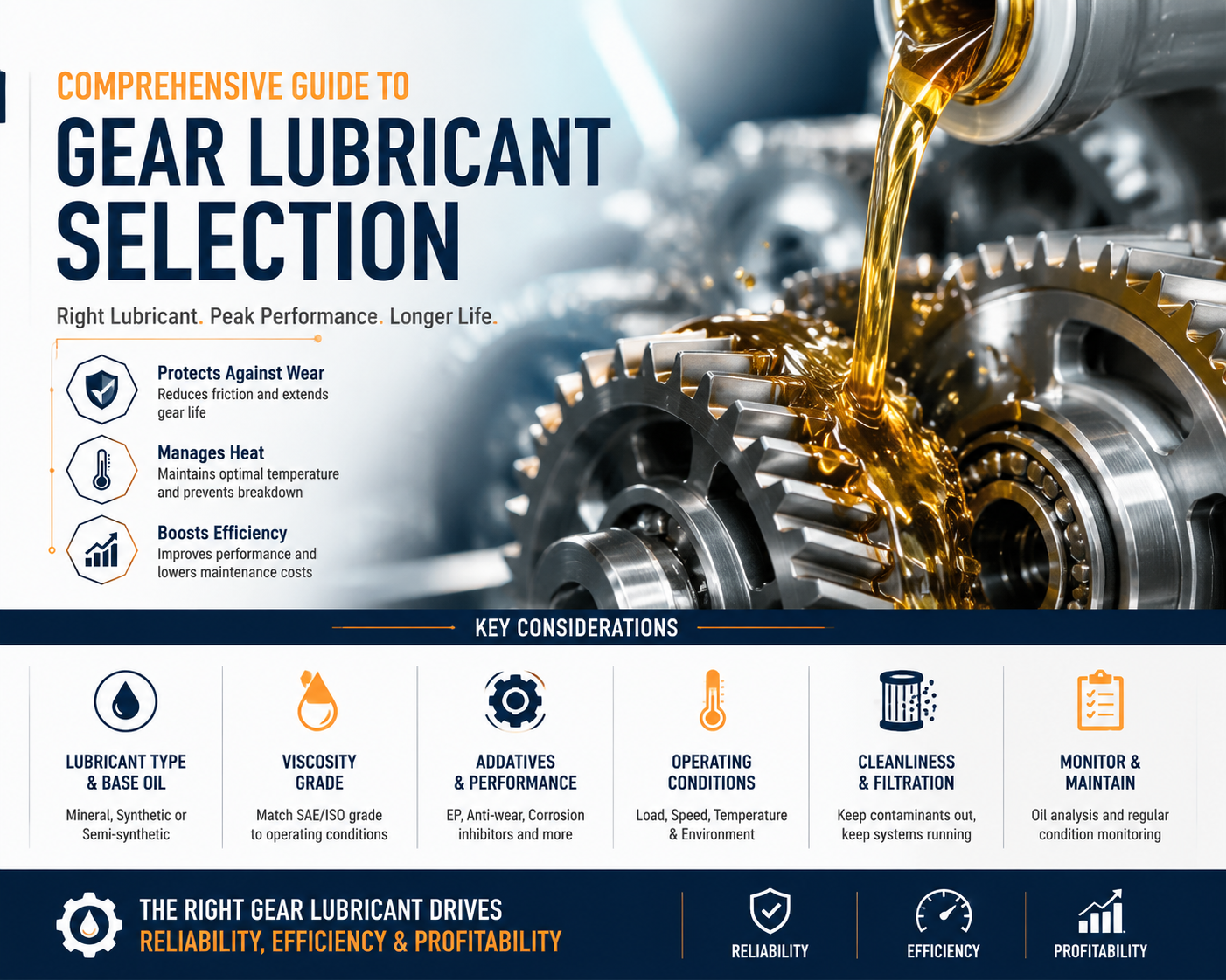
Efficient lubrication systems play a central role in minimizing frictional losses and reducing wear. Synthetic gear oils with high film strength provide superior protection during high-load operation.
Surface finishing quality also influences friction behavior. Smooth tooth surfaces reduce asperity interaction and improve operational efficiency.
7.3 Noise and Vibration Reduction Strategies
Noise reduction remains a major design objective in modern machinery. Engineers employ optimized tooth modifications, precision balancing, and advanced housing isolation techniques to reduce acoustic emissions.
Spiral bevel gears are particularly effective at minimizing vibration due to their progressive tooth engagement characteristics.
8. Bevel Gear Calculations
8.1 Calculating Pitch and Tooth Dimensions
Accurate pitch calculations ensure proper tooth engagement and load distribution. Engineers use mathematical formulas based on module, diametral pitch, and pressure angle to determine optimal tooth geometry.
Even small dimensional inaccuracies can compound rapidly during operation, producing excessive backlash and vibration.
8.2 Determining Center Distance
Center distance calculations establish the spacing between gear axes and significantly affect meshing accuracy. Incorrect center distance selection can disrupt contact patterns and reduce efficiency.
Precision assembly procedures help maintain proper alignment throughout the gearset lifespan.
8.3 Efficiency and Power Transmission Calculations
Mechanical efficiency calculations evaluate energy losses caused by friction, heat generation, and dynamic loading. High-quality bevel gear systems often exceed 95% transmission efficiency under optimal operating conditions.
That level of efficiency may not sound flashy, but over thousands of production hours, it saves enough energy to make accountants grin ear to ear.
9. Manufacturing Processes
9.1 Gear Cutting Techniques
Bevel gear cutting requires specialized machinery capable of generating complex tapered tooth geometry. Common methods include face milling, face hobbing, and generating processes using precision cutters.
Advanced cutting techniques improve dimensional consistency while reducing surface roughness and machining errors.
9.2 CNC Machining for Precision
Computer numerical control machining has transformed bevel gear production by enabling micron-level precision and repeatability. Multi-axis CNC systems can manufacture intricate tooth profiles with remarkable accuracy.
Automated machining also reduces production variability, improving overall gear reliability.
9.3 Heat Treatment and Finishing
Heat treatment enhances hardness, wear resistance, and fatigue strength. Finishing operations such as grinding and lapping improve tooth surface quality and contact accuracy.
These finishing stages may seem tedious, but skipping them is like trying to win a pickleball tournament wearing work boots — technically possible, but definitely not advisable.
10. Quality Control and Testing
10.1 Visual and Dimensional Inspection
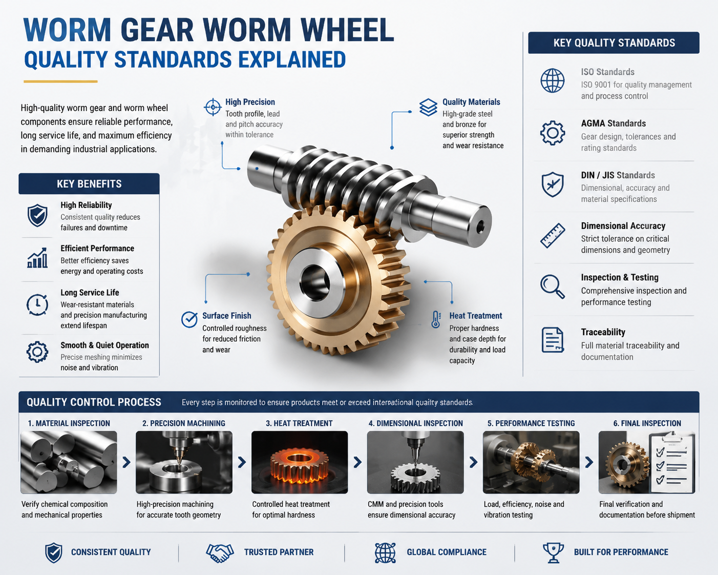
Quality inspectors evaluate bevel gears for dimensional accuracy, surface defects, and manufacturing inconsistencies using coordinate measuring machines and optical scanning equipment.
Inspection procedures verify compliance with engineering tolerances and industry standards.
10.2 Performance Testing Under Load
Load testing simulates real-world operating conditions to assess thermal stability, vibration behavior, and torque transmission capability. Engineers monitor gear contact patterns and acoustic performance during these evaluations.
Testing reveals potential weaknesses before equipment enters production environments.
10.3 Durability and Lifespan Assessment
Durability testing evaluates long-term resistance to fatigue, pitting, and abrasive wear. Accelerated life-cycle testing helps manufacturers estimate operational lifespan under varying conditions.
Reliable lifespan prediction reduces maintenance uncertainty and improves operational planning.
11. Industrial Applications of Bevel Gears
11.1 Automotive and Transportation Machinery
Automotive differentials rely heavily on bevel gears to transfer power between axles while accommodating varying wheel speeds during cornering. Heavy trucks, locomotives, and marine propulsion systems also utilize bevel gearing extensively.
Without these gears, modern transportation systems would be dead in the water, plain and simple.
11.2 Aerospace and Defense Equipment
Aircraft control systems, helicopter transmissions, and military vehicles require lightweight yet highly durable bevel gear assemblies capable of surviving extreme operating conditions.
Precision manufacturing and rigorous testing standards are essential in aerospace applications where reliability margins are exceptionally narrow.
11.3 Heavy Machinery and Construction Tools
Mining equipment, excavators, crushers, and industrial conveyors frequently employ bevel gears for directional power transfer. These environments subject gears to immense shock loads, abrasive contamination, and continuous duty cycles.
Robust gear design ensures machinery remains operational even under punishing field conditions.
12. Advantages of Using Bevel Gears
12.1 Efficient Power Transmission
Bevel gears provide highly efficient torque transfer between intersecting shafts while minimizing energy losses. Properly designed systems deliver excellent mechanical performance across a wide range of operating conditions.
12.2 Compact and Versatile Design
Their compact geometry allows engineers to create space-efficient machinery layouts. Bevel gears can accommodate numerous shaft orientations and design configurations.
That versatility gives designers more freedom than a wide-open pickleball court on a sunny Saturday morning.
12.3 High Torque Handling Capability
Heavy-duty bevel gears can transmit substantial torque loads while maintaining structural integrity. Advanced materials and optimized tooth geometry further enhance load-carrying capacity.
13. Challenges in Bevel Gear Design
13.1 Complex Manufacturing Requirements
Bevel gear production requires highly specialized machinery, advanced tooling, and skilled operators. Maintaining dimensional precision across tapered tooth profiles presents significant manufacturing challenges.
13.2 Alignment and Installation Issues
Improper alignment can severely impact performance, causing uneven wear, vibration, and premature failure. Installation accuracy remains critical throughout the assembly process.
A tiny alignment error today can snowball into a full-blown mechanical fiasco tomorrow.
13.3 Maintenance and Lubrication Considerations
Continuous lubrication is essential for minimizing friction and preventing surface damage. Contaminated lubricants can rapidly accelerate wear and reduce operational lifespan.
Routine inspection schedules help identify developing issues before catastrophic failure occurs.
14. Innovations in Bevel Gear Technology
14.1 Advanced Materials and Coatings
Emerging materials such as powder metallurgy alloys and ceramic composites offer improved strength-to-weight ratios and enhanced thermal resistance. Advanced coatings reduce friction and improve wear performance.
14.2 3D Printing and Additive Manufacturing
Additive manufacturing technologies enable rapid prototyping and low-volume production of complex bevel gear geometries. Engineers can quickly evaluate design modifications before committing to full-scale manufacturing.
This technology is changing the game faster than a sneaky third-shot drop catches opponents flat-footed at the kitchen line.
14.3 Smart Sensors and Predictive Maintenance
Embedded monitoring systems now track vibration, temperature, and lubrication conditions in real time. Predictive maintenance algorithms analyze operational data to forecast component wear and schedule service proactively.
For more information on predictive maintenance technologies, visit NIST.
15. Tips for Optimizing Bevel Gear Performance
15.1 Proper Lubrication and Cooling
High-performance lubricants reduce friction, dissipate heat, and protect tooth surfaces from wear. Cooling systems further improve operational stability during high-speed operation.
Additional tribology resources are available through The Society of Tribologists and Lubrication Engineers.
15.2 Correct Installation Techniques
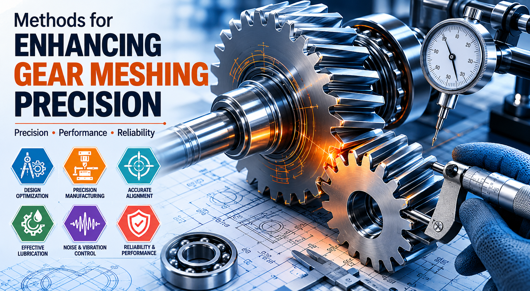
Proper installation procedures ensure accurate alignment and balanced load distribution. Precision measurement tools help maintain correct backlash and contact patterns.
Rushing the installation process is basically asking for trouble down the road.
15.3 Regular Inspection and Replacement Schedule
Routine inspections help identify pitting, scoring, and lubrication degradation before serious damage occurs. Preventive replacement schedules reduce unplanned downtime and improve operational reliability.
16. Case Studies
16.1 Successful Implementation in Automotive Systems
Automotive manufacturers have achieved substantial drivetrain efficiency improvements through optimized spiral bevel gear designs. Enhanced tooth geometry and advanced heat treatments have reduced friction losses while increasing durability.
16.2 Efficiency Improvements in Industrial Machinery
Industrial processing facilities have reported lower energy consumption and reduced maintenance costs after upgrading to precision-ground bevel gear assemblies. Improved lubrication systems further extended operational lifespan.
Those savings may start as small potatoes, but over years of continuous production, they stack up like cordwood.
16.3 Lessons Learned from Design Failures
Historical gear failures often reveal common design shortcomings such as inadequate lubrication, improper material selection, or insufficient alignment control. These lessons continue shaping modern engineering standards.
Additional engineering standards and references can be found through The American Gear Manufacturers Association.
17. Future Trends in Bevel Gear Design
17.1 Automation and Robotics Integration
Automation systems increasingly rely on precision bevel gears for compact robotic motion control. Demand for lightweight, high-efficiency gear assemblies continues expanding across manufacturing industries.
17.2 Lightweight and High-Strength Materials
Material science advancements are enabling the development of lighter yet stronger gear components capable of operating at higher rotational speeds with reduced inertia.
Research on advanced materials can also be explored through NASA.
17.3 AI-Driven Design Optimization
Artificial intelligence tools now assist engineers in optimizing tooth geometry, stress distribution, and manufacturing parameters. AI-driven simulations reduce development time while improving gear performance predictions.
This fusion of computational intelligence and mechanical engineering is steering the industry toward remarkably sophisticated drivetrain solutions.
18. Conclusion
18.1 Summary of Bevel Gear Types and Applications
Bevel gears remain foundational components in modern power transmission systems, offering reliable angular torque transfer across countless industrial applications. Straight, spiral, and Zerol bevel gears each provide unique advantages suited to specific operational demands.
18.2 Key Takeaways for Industrial Efficiency
Proper material selection, precision manufacturing, optimized lubrication, and accurate installation procedures all contribute significantly to gear efficiency and longevity. Engineers who prioritize these factors can dramatically improve machinery performance while reducing operational costs.
For foundational information on gear mechanics, visit Wikipedia's Bevel Gear Reference.
18.3 Encouragement to Implement Design Best Practices
As industrial systems continue evolving toward higher efficiency and greater automation, bevel gear technology will remain a cornerstone of advanced mechanical engineering. Organizations that invest in robust bevel gear design practices position themselves for stronger reliability, improved energy efficiency, and long-term operational success.
At the end of the day, great machinery is not built on luck — it is built on meticulous engineering, disciplined maintenance, and components tough enough to handle the grind without blinking.